 English
  한국어
한국어  português
  العربية
  tiếng việt
  ไทย
ไทย  Malay
Malay  हिंदी
हिंदी  Indonesia
  বাঙালি
  اردو
اردو 
Five Things You Should Know About Weft feeder/Accumulator
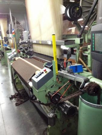
When weft thread is unwound intermittently and directly from the relatively uneven surface of a weft cone, sharp, dynamic tensions will occur due to sudden weft movement at the beginning, increasing weft breakage and affecting the fabric quality. To reduce the tension change during weft axial unwinding from the package, and enable weft yarn passes through the shed with constant tension, the weft feeder(or weft accumulator) is invented. In modern weaving processes, weft feeders are widely used where high-speed yarn unwinding is required, such as various shuttleless looms and weft knitting machines. Here are five things you should know about weft feeders.
1 Yarn Storage Requirements
After unwinding from the cone package, the weft winds onto the storage drum. To reduce the unwinding resistance, the storage drum is designed in the shape of a smooth surface cylinder or conical drum. Generally, before weft insertion, a certain amount of yarn storage is required on the yarn storage drum. The yarn storage speed is automatically adjusted according to how much yarn is existing on the drum. The weft yarns are arranged in an orderly spiral shape on the drum, to ensure sufficient yarn storage and facilitate unwinding. To organize and unwind the weft in an orderly manner, and ensure the necessary tension during the weft insertion process, a tensioner and a tension ring are respectively installed at the yarn inlet and the separation of the yarn from the drum surface. Finally, to prevent the twist of the yarn during the winding process, the weft yarn on the storage drum should have two different winding directions to meet the S-twist and Z-twist needs.
2 Weft Yarn Winding, Guiding, and Unwinding
The yarn is to be wound onto the drum in a spiral shape. For this, a winding movement and guiding movement are required. There are two types of winding: dynamic drum winding and fixed drum winding. The yarn guide is divided into two types: positive yarn arrangement and negative yarn arrangement. The unwinding mode can be two types-- fixed-length and non-fixed-length. The fixed-length type is suitable for air-jet and water-jet looms; the non-fixed-length type is suitable for rapier looms and projectile looms.
Winding
(1) Dynamic drum winding
The appearance of the dynamic drum winding weft feeder and the yarn winding method is shown in below Figure 1. During winding, the yarn storage drum oscillates helically, winding the yarn sent by the tensioner 1 onto the yarn storage drum 2. To proceed fluent winding, the leading end of the weft yarn must be attached to the rotating drum surface. Due to the brush 3, the weft yarn only slides along the drum surface during unwinding, and the tension is relatively uniform. However, the brush is easily damaged under the strong abrasion from weft yarn. Weavers should pay attention to the cooperation of the brush and the twist direction of the weft yarn during the operation.

Figure 1 Dynamic drum winding weft accumulator
1-Tensioner 2-Yarn storage drum 3-Brush
The brush's function is to avoid the formation of thread loop caused by yarn unwinding, and should not be used to adjust the output tension.
Increasing the diameter of the storage drum will add the drum's rotational inertia, which is not conducive to starting, braking, and high-speed running; reducing the diameter of the drum will increase the number of weft coil and increase the length of the drum. Usually, the diameter of the yarn storage drum is about 130mm.
The dynamic drum winding weft feeder has a complicated structure. The weft coil on the drum surface is easy to overlap, especially for low-twist yarns, of which the yarn pitch is small and easy to stick, and the yarn storage volume is limited. It is suitable for weft insertion rate below 1000m/min and reed width less than 2 meters.
(2) Fixed drum winding
Figure 2 shows the structure and winding method of the fixed drum winding weft feeder. When winding the yarn, the light-weight winding disk 1 conducts rotary motion, and the weft is wound onto the fixed storage drum 2 through the yarn guide tube therein. The yarn storage drum is looped on the transmission shaft 3, and is attached to the machine body by the permanent magnet 4. When the weft yarn is unwound from the drum surface, it can maintain a uniform tension under the action of the tensioner. For devices using tension rings, pay attention to the pinna's arrangement in the rotation direction of the tension ring, which must match the twist direction of the weft yarn.

Figure 2 Fixed drum winding weft accumulator
1-Winding disk 2-Fixed storage drum 3-Transmission shaft 4-Permanent magnet
The fixed drum weft feeder has a simple structure and a big yarn storage capacity, and is suitable for weaving machines with weft insertion rate over 1000m/min and a reed width over 2 meters.
Yarn guiding mode
The arrangement requirements for each specific weft yarns are different. Ordinary weft yarns are allowed to be closely arranged on the storage drum. Flat yarns and knot yarns are not allowed; they are requested to be arranged on the storage drum with intervals, to prevent the thread from sticking when unwinding. Due to this, the yarn guiding mode is divided into negative yarn arrangement and positive yarn arrangement.
(1) Negative yarn arrangement
When the negative yarn arrangement is adopted, there is no unique yarn guide mechanism to arrange the yarn coils in an orderly manner along the axis of the yarn storage drum. Whether the yarn can form an orderly arrangement depends entirely on the taper and smoothness of the drum surface, the tension and elasticity of the yarn itself, and the coefficient of friction between the weft and the drum surface.
When a cylindrical drum is used, the tapered surface at the end of the yarn storage drum can push the yarn along the cone surface onto the drum surface under the squeezing force generated by the yarn tension during rotation. When the angle a between the cone surface and the drum surface is 135° (Figure 10-1), the squeezing force of the yarn coil is the best, so this angle is mostly used for the dynamic drum weft accumulator. But this mode of yarn arrangement is easy to cause overlapping of yarn coils. When a conical drum is used, the yarn's diameter decreases as the yarn coil moves forward along the drum surface, and the yarn tension decreases accordingly.
(2) Positive yarn arrangement
In positive yarn arrangement, weft coils are driven by a unique yarn arrangement mechanism and move along the drum surface. The yarn coils discharged by the yarn arranging mechanism have two patterns--compact pattern and spacing pattern.
The compact mechanism is composed of a transmission shaft, an eccentric inclined shaft sleeve and a swashplate. When the transmission shaft rotates, the eccentric inclined shaft sleeve also rotates together. There is a radial long groove in the swinging swash plate of the looper, and the positioning claw fixed on the yarn storage drum is inserted into the long groove. As the swash plate is constrained by the swash sleeve and positioning claws, the swash plate generates a wave-shaped swing, pushing the yarn sent from the yarn guide tube in the winding disc to the surface of the storage drum, and actively pushing the yarn coils, hence forming a regular compact arrangement on the drum surface. However, for flat yarns and knotted yarns, spacing pattern yarn arrangement is required.
The spacing pattern yarn arrangement is classified into two types: oscillating inclined drum type and screw type. The space between the yarn coils discharged by these two yarn arranging mechanisms is not adjustable, generally between 0.8~2.1mm.
The oscillating inclined drum-type yarn arranging mechanism has been widely used. The mechanism is shown in Figure 3, its transmission principle is similar to the above-mentioned swinging swash plate type, except that the wave-swinging swash drum is used instead of the wave-swinging swashplate. The inclined drum and the yarn storage drum are designed in the form of grid rods, nested with each other, and there is a large gap between each grid rods. The oscillating inclined drum lifts upward, bring out weft coil from the storage drum, and the oscillating drum swings forward to move the weft coils along the drum surface, and then the oscillating inclined drum swings back to the starting position below the yarn storage drum. By repeating the above movements, the yarn coils are arranged regularly on the drum surface in equal intervals, without overlapping and tangling, and the pitch of the weft yarn can be continuously adjusted.

Figure 3 Oscillating inclined drum-type yarn arrangement mechanism
Unwinding
(1) Fixed-length unwinding
For jet loom, the yarn is inserted into the loom shed by air or water pressure. As the length of the jet weft insertion is difficult to determine, the weft accumulator needs to limit unwinding yarn coils according to the loom's weaving width. The fixed-length device (also called electromagnetic needle) on the weft feeder plays this role. The microprocessor on the jet loom calculates the time required for unwinding based on the jet flow rate and the preset traverse distance. It controls the timing of electromagnetic needle lifting and lowering. The interval between the lifting and lowering of the electromagnetic needle is unwinding time. This is called time-measured fixed-length unwinding. In most cases weft feeder with coil-measured fixed-length unwinding is applied due to its accurate control of weft quantity, such as ROJ S and Elf electronic weft feeder.
(2) Non-fixed length unwinding
Unlike jet looms, rapier looms, and projectile looms have a weft clamping device; the clamping device on the weft insertion mechanism traverse in a fixed stroke. The weft feeder only needs a tensioner and a damping ring at the unwinding end to offer a certain tension and resistance, so that the feeder can cooperate with the loom. In this way, no complicated fixed-length device is needed.
3 Tension Device
Except for the tension device installed at the weft entering spot, tension device is also equipped at the place where the weft yarn is exiting point from the drum surface. Commonly used tension devices are shown in Figure 4. The tension device at the weft exit should be selected for use according to the difference in weft yarn twisting fineness. Fixed drum and dynamic drum weft feeders often use tension rings.

Figure 4 Tension device for weft accumulator
If the tension of the tension device at the weft entering spot is too small, it will lead to weft yarn excessive sliding on the drum surface. When the yarn coil fills the entire drum surface, it will cause overlap of the subsequent weft coils. If the tension is too big, the weft sliding resistance on the drum surface will increase, which will also cause the excessive tight arrangement of the subsequent yarn coils, and even cause the weft coils to overlap. The tension device specifications should be selected according to factors such as the weft yarn spec and the installation position of the tension device (Table 10-1).
IRO has done a lot of research on tension devices, and there are various types of tension devices for choosing.
4 Weft Storage Control
Weft storage control is completed by the weft yarn storage detector on the weft storage drum and the central microprocessor. Weft feeder can realize the control of weft yarn pre-winding, yarn storage winding speed, and weft breakage alarm.
Weft pre-winding control
The weft storage drum always reserves a certain amount of weft yarn in advance, the amount of which is set according to the weaving plan. It is operated through the pre-winding control switch on the weft feeder, such as the OFF/ON switch on LASER/NOVA weft feeder, the pre-winding switch on FDP weft feeder.
Weft storage volume detection and winding speed control
The weft feeder detects the weft reserves through photoelectric sensors and mechanical sensors. Currently, magnetic hall sensors are mainly used for detection (Figure 10-5), with the features of high sensitivity, reliable operation, and long life. Take the magnetic probe of LASER/NOVA feeder as an example; if the weft yarn overtakes the magnetic probe, then there is a certain amount of yarn storage. Magnetic probes in any positions are overtaken or erected, will be detected by the sensor. The microprocessor determines the weft feeder's working state according to the detection result: acceleration, deceleration, or shutdown.
The weft feeder for the jet loom determines the winding speed based on the comparison between the preset number of unwinding coils and the current number of windings. If the preset angle weft insertion is to unwind 4 loops in each weft insertion, the number of windings output by the encoder sensor should also be 4 loops in each electromagnetic needle lift. If less than 4 loops, winding accelerates; if more than 4 loops, winding decelerates.

Figure 5 Weft detection on oscillating inclined drum-type accumulator
Weft breakage control
Weft breakage is detected by the weft breakage sensor mounted at the tail of the weft feeder. Once weft breakage is detected, the signal is immediately sent to the loom for automatic weft change or stop.
5 Application and Maintenance
Application
The LASER/NOVA weft feeder is equipped with front and rear end tensioners. In the application, the clamping tension should be adjusted according to the features of the weft yarn, and the degree of the brush ring should be also adjusted. The weft spacing of different yarn counts can be adjustable, as per the user instructions.
In the use of the FDP weft feeder, the first thing is to adjust its position so that the axis is in alignment with the main nozzle of the loom. Adjust the drum diameter according to loom width, and adjust the distance between the electromagnetic needle and the main drum lamella, to meets the conditions of use.
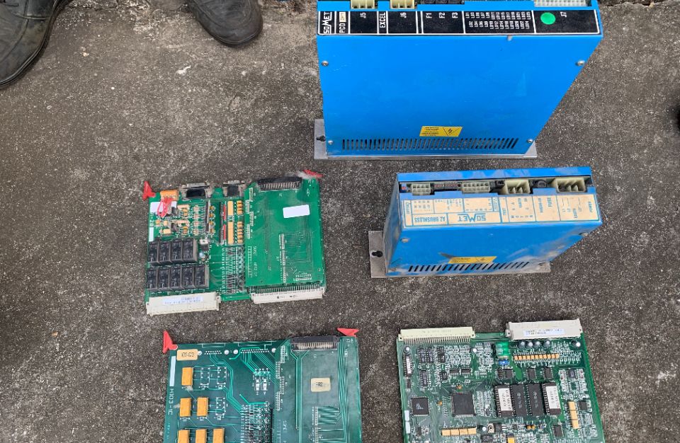
In the application of the COMET weft feeder, to avoid the impact from vibration, the weft feeder should be installed on a stand away from the loom, with its axis line in alignment with the main nozzle of the loom. The distance between the weft feeder and the main nozzle is preferably about 350mm to ensure the best weft insertion condition.
Maintenance
The LASER/NOVA type weft feeder needs regular maintenance, mainly to clean up the flying, fluffy, and dust on the yarn storage drum to ensure the flexibility of the small magnet. The purpose of this is to ensure the proper operation of the weft detector and ensure the smooth running of the weft accumulator.
The FDP weft feeder's maintenance is to periodically fill the oil filling hole to ensure that the cantilever shaft rotates quickly. The cleaning of the drum surface is also essential. It can protect the drum surface from dust and extend the life of the drum.
During the use of the COMET weft feeder, the flying fluffy and dust should be cleaned regularly to ensure the smooth operation of the device and reduce the failure rate.