 English
  한국어
한국어  português
  العربية
  tiếng việt
  ไทย
ไทย  Malay
Malay  हिंदी
हिंदी  Indonesia
  বাঙালি
  اردو
اردو 
All You Need to Know About Electronic Weft Selector
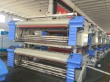
Multi-color weft selection is one of the features of shuttleless loom. The weft selection device, or weft selector, color selector, is an integral part of the loom. There are two types of weft selectors--mechanical and electronic. Here is all you need to know about the electronic weft selector.
Function of the Electronic Weft Selector
The electronic weft selector is an essential component in the weft insertion system of rapier weaving. It consists of two parts--weft selection signal device and weft selection actuator. Weft color cycle instructions are designed according to the requirements of the fabric technique, and the instructions are sent to the weft selection signal device. Upon receipt of instruction signal(power on and off), the transmission mechanism steers a group of weft selection fingers holding weft yarns to enter the working position. The weft yarns then fall into the rapier clamp when the rapier head traverse toward the shed. This is the realization of multi-colors weft selection and different styles of fabrics.
Types and Technical Requirements of Electronic Weft Selector
With the advancement of science and technology, electronic technology has been widely used. In recent years, the rapier loom has been further improved in the level of automation. The weft selection device has also developed from the original mechanical color selector to the current electronic weft selector.
Types of electronic weft selector
1. Weft selection finger driven by step motor
This is the most advanced form in the world today; applied on rapier loom like Picanol's GAMMA, Sinotextile's DF31 and DF51.
It is driven by independent modules, each module composed of an independent stepping motor and weft selection finger, up to 16 colors. As the selector is controlled directly by the loom microcomputer, it can synchronize with the loom speed and weft repeat. Weft yarn movement is straight and maintained in constant low tension. Weaver can set the best threading position. Each module can be interchanged. As there is no mechanical movement, so no lubrication maintenance is required,
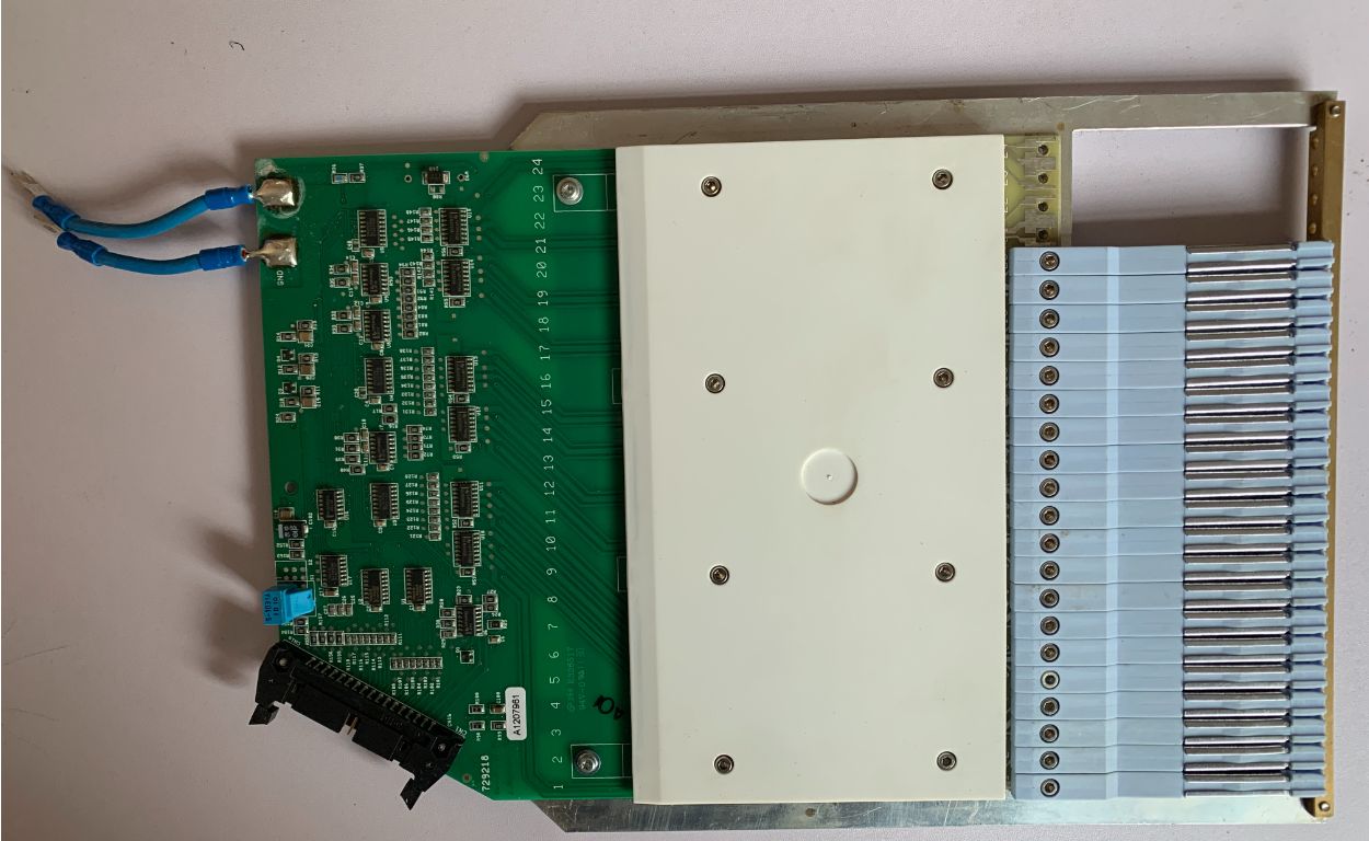
hence more suitable for high-speed weaving, see Fig 1.

Fig.1 Structure of Electronic Color Selector
2. Weft selection finger driven by a linear motor--from Somet and Vamatex
TM11E Super Excel rapier loom produced by Italy PROMATECH, Lenardo rapier loom, the K88 rapier loom, and the G6300 rapier loom produced by Sulzer all use the linear motor type weft selector developed by themselves. It has a compact structure, small size, easy to operate, and suitable for high speed, stable running. Our weft selector has been widely applied in domestic loom manufacturers.
3. Electromagnetic weft selector
Most of the rapier looms use electromagnetic electronic color selector, such as models of SM93, C401, P401, FAST, GTM, THEMA11E. This type of weft selector is suitable for medium and high-speed weaving. At present, this device has been mass-produced in our company, with stable quality, relatively low cost, and less machine spare consumption.
Take FAST electronic weft selector as an example to explain the working principle of electromagnetic weft selector. The electronic weft selector is equipped with multiple weft selection fingers, which can select a variety of weft yarns. The electronic weft selector controls the weft selection sequence according to the electric signal.
The main components of the weft selector are shown in Fig 2. The rotation of the cam 28 is realized through the transmission of the loom pulley.

Fig.2 FAST Electronic Color Selector Schematic Diagram
When the electric signal is sent to the electromagnet 10, the stopper 29 is sucked down when the electromagnet is magnetized. When the cam turns to a certain angle, the cam 28 pushes the push rod 30, so that the inclined surface of the lower end of the connecting rod 31 contacts the end surface of the push rod, forming a fulcrum so that it swings back around the fulcrum. The rocker arm 32 is rotated by the connecting rod 31 to move the weft selection finger 19 downward, and the weft selection finger sends the weft yarn to the clamp of the rapier head. When the electromagnet 10 is not energized, the stopper 29 is released by the action of the spring 33. At this time, the connecting rod 31 has no fulcrum, and the weft selector does not feed weft.
The technical requirements of electronic weft selector
Below are the main technical requirements of the electromagnetic weft selector--
1. In each rotation of the main shaft, only one weft selection finger should work. The weft selection finger should work cyclically, continuously and steadily according to the set procedure. There should not be two weft selection fingers work simultaneously or intermittently.
2. All the connecting shafts of the electromagnetic weft selector should rotate flexibly without blocking.
3. The height and height difference of all weft-selecting fingers should conform to the loom's setting value, without collision to fixed rails, to ensure that the weft yarn can be guided to the clamp of the rapier head. For example, SM93 electronic weft selector height difference ≤ 6mm, THEMA11E electronic weft selector height difference 28 ~ 33mm, FAST electronic weft selector height difference ≤ 6mm.
4. The suitable voltage of the core coil, or electromagnet, of electromagnetic weft selector is 24~30V DC. After continuous operation, the coil temperature rise should be ≤25℃; the electromagnet suction force should be more than two times of the electromagnet's spring pressure.
5. Rated running speed, vibration, empty running noise pressure level, and empty running power consumption value are all decided by the loom's overall design index. The designed parameters of the current domestic-made middle and high-grade loom are as follows: FAST type: running speed 600r/min ; Empty running noise pressure level ≤78dB; empty running power consumption ≤65W. Vibration x≤1.5/cm/s; y≤1 cm/s; z≤1 cm/s.
SM93 type: running speed 400r/min; empty running noise pressure level ≤86dB; empty running power consumption ≤65W. Vibration x≤3cm/s; y≤3cm/s; z≤3 cm/s.
6. During the operation of electronic weft selector, no oil leakage or oil leakage shall occur.
7. The surface of the electronic weft selection device must be free from bruising and damage, and the paint layer should be smooth and free of flaking.
8. The lubrication method of the electronic weft selector is determined by the overall design structure of the loom. Generally, there are two types of lubrication-- the entire oil bath type and the joint oil injection hole type. The specific choice of lubrication grade should be specified. Generally, No. 20 motor lubrication, calcium-based grease are used.
Use of Electronic Weft Selector
The use and adjustment methods of different electronic weft selectors are determined according to the loom manufacturer's overall structure and design. Below are the notices that weaver should take care in the use of electronic weft selector.
1. According to the requirements of the weaving machine commissioning manual, position the electronic weft selector on the loom installation board and fix it. Check whether the coil and socket wiring meets the relevant wiring requirements of the loom. The number of sockets, weft selection fingers, and each wire's color should be consistent to ensure that weft selection instruction is accurate.
2. Check and adjust whether all connecting pieces rotate flexibly and whether the tightening screws are fixed firmly.
3. Check whether the height difference of the weft-feeding height of all weft-selecting fingers meets the requirements of the weaving machine commissioning manual.
4. Check whether the clearance between the electromagnet and the electromagnetic suction piece meets the loom commissioning manual.
5. Check whether the clearance between the selection hook and the swing rod meets the commissioning manual's requirements.
6. Manually rotate the loom main shaft for one cycle and observe whether the weft selection finger works only once; after loom starting, check whether the weft selection finger selects the weft according to the stipulated program. Check whether the scissors arm and scissors cut the weft yarn properly.
7. Whether the lubrication level meets the requirements.
Maintenance and Management of Electronic Weft Selector
Maintenance and care
To ensure the reliable function of the electronic weft selector and keep it in an excellent performance condition, each user must conduct the necessary maintenance and adjustment according to the use and maintenance manual provided by the loom manufacturer to prevent damage during use.
The below are the maintenance requirements of the electronic weft selector of the TM11E rapier loom.
1. Internal adjustment
The following adjustments should be made during routine maintenance or when the internal components of the electronic weft selector malfunction.
A. 0-degree position, when adjusting, adjust the correct gap by the reference degree (0°, 28°, 100°) indicated by a dial on the left side of the weft selector. It is done through a magnet device.
Position adjustment--this position indicates that the picking finger is raised to the highest point, and the loom is at 315° or 325°. The specific adjustment steps are: inserting the gauge provided with the weft selector between magnet A and selection hook suction piece B. Loosen the fixing screw and rotate the cam C to increase or decrease the distance between the magnet A and the suction plate B to keep the distance at 0.5mm.
If you want to change the carbon supply device, you must remove the bracket's magnet device, leaving the gasket and bracket originally installed between the electromagnet connection and the bracket. The new electromagnet must be installed with all the original gaskets. On the original bracket. Electromagnets and supports are not interchangeable. Because the number of shims varies according to the structural tolerances of the weft selector.
Adjustment of the position of the rocker arm F and the selection hook G (Figure 3): At the 0 position, the gap distance between the rocker arm F and the selection hook is 1.8mm. If not, adjust the cam. Turn the cam forward to increase the gap. Turn back to reduce the gap, and check the rule to keep it vertical.
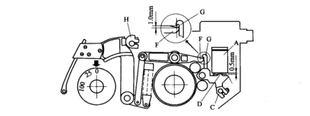
Fig.3
B. Position 100: At position 100, the positions of the rocker arm and the selection hook are shown in Figure 4.
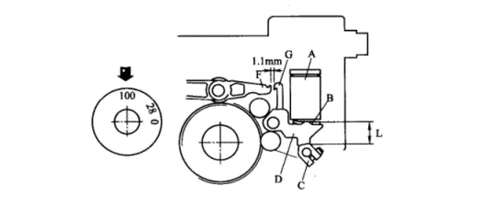
Fig.4
Ensure the front adjustment, the distance between the rocker arm and the selection hook is 1.1mm, and the allowable tolerance is +0.2mm/-0.1mm. If this requirement is not met, you should readjust and check the C and D cams at the same time. Wear (if wear occurs, the 0.5mm value is no longer considered).
To this end, make sure that the cam L (Figure 5) is at the lowest point. There is a reference line on the L point M of the cam. Turn the camshaft so that the bearing on the cam is on the same line as M.
Loosen the two screws N at the end and adjust the cam P until the bearing R no longer rotates freely (there is no gap between the bearing and the cam). Use two fingers to gently turn the bearing.
When making the above adjustments, pay particular attention to that there should be no gap between the cam L and the bearing. The pre-pressure should not be too large to avoid bearing wear.
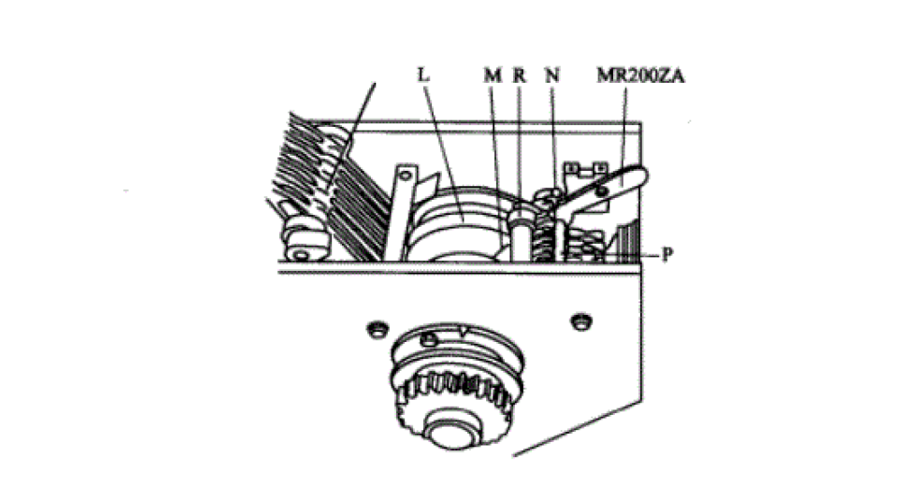
Fig.5
2. Maintenance cycle of electronic picking device
Carrying out regular and systematic inspections of electronic weft selection devices is the most important auxiliary work. These preventive inspections can avoid many failures and damages. The maintenance and repair contents are shown in the table below.
|
Life
Cycle |
Working
Time |
Maintenance
Content |
|
First
cycle |
Every
beam change |
1 Cleanning by
compressed air 2 Clean the weft selecting fingers, remove fluff and flying |
|
Third
cycle |
800
working hrs |
1 Check
transmission gear meshing clearance and add grease |
|
Fourth
cycle |
3500
working hrs |
1 Check the shaft transmission belt tension and
belt wearing status 2 Carry out a thorough checking over the inside parts of color selector and adjust, to make sure all data conform to requirement |
|
Fifth
cycle |
5000
working hrs |
Replace
all the grease of color selector, and clean metal filling on the magnetic
filter |
Warehouse Management
1. After the OEM purchases the electronic weft selector device, it should be inspected one by one or by random inspection, and stored in the original box, neatly stacked.
2. Pay attention to the stacking order, and implement the principle of first entering the warehouse and using first, and can not store it for too long. Spot check every six months, and then do the oil seal work (coat anti-rust oil) according to the situation.
3. For the electronic selection device that the factory mechanics cannot troubleshoot, the mechanic must fill out the fault phenomenon, hang the label, store it separately, and notify the supplier to repair it in time.